The West Kowloon Masterplan, Second Stage Competition
Hong Kong, China, 2003-2004
Foster + Partners
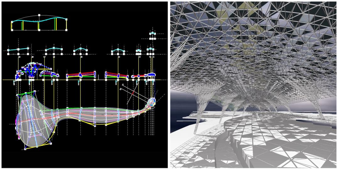
Image Source: Brady Peters / Foster + Partners
The West Kowloon Masterplan was the project I first worked on when I joined the office. In this project I was responsible for the development of the form and structure of the Great Canaopy. The West Kowloon Cultural District Masterplan was a vast project encompassing amazing residential towers, a huge park with views across the water to downtown Hong Kong, several layers of retail development, and several landmark cultural buildings including museums, theatre, arena, and open amphitheatre. The park was covered by the Great Canopy. A 1500 metre long roof that acted as an environmental modulator - protecting inhabitants from sun, rain, and modifying the temperature and mico-climate. This dragon-like roof acts as a landmark for West Kowloon and Hong Kong, being very visible in the harbour and from both cities.
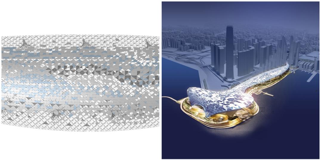
Image Source: Brady Peters / Foster + Partners
The roof spans only five or six metres in its smallest point and expands to a 120 metre span in the head area. The environmental analysis was linked to the geometric model through a 2D drawing. A computer program was written that analyzed the 2D environmental set out done by the engineers and translated this to the 3D CAD model. There were six different panel types that were arrayed according to the environmental strategy. The roof panels generated electricity through photovoltaics, allowed views with glazing, sun shading through solid and louvred panels, changed microclimactic conditions through wind-scoops, and had lightweight protection through inflated plastic cushion panels.
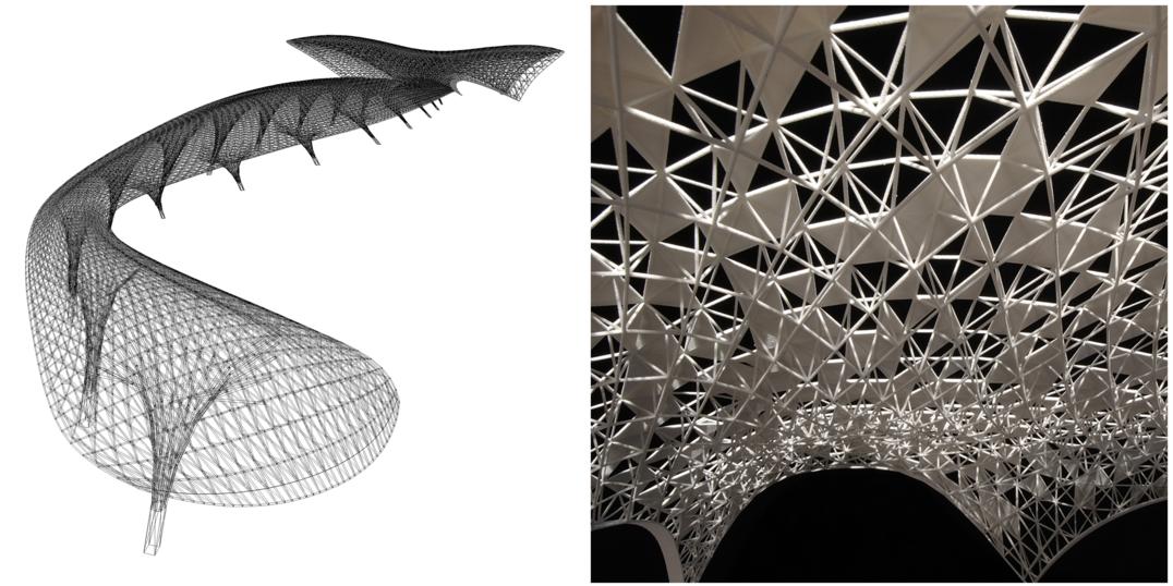
Image Source: Brady Peters / Foster + Partners
The design of the roof, structure, and panel systems required the use of several different parametric design systems. The form was developed using 2D profiles in Microstation's Dimension Driven Design (DDD) system, which were then arrayed in 3D to create a series of smooth surface patches. These surface patches were then used to create an sequential array of top and bottom surface profiles which could then be used to create a single top and bottom surface. These top and bottom surfaces were then used in a custom computer program that generated the spaceframe and placeholder panels from these surfaces. It was necessary to use the program to draw the structure of this roof. In this way the I could design a system, encode these relationships, and then use the computer to populate the surfaces with many thousands of instances of these architectural systems. This task would have been impossible to draw by hand. This was the first use of Microstation VBA programming interface in the office, which has proven to be a hugely successful and adaptable tool for skilled architectural designers to create their own design tools.
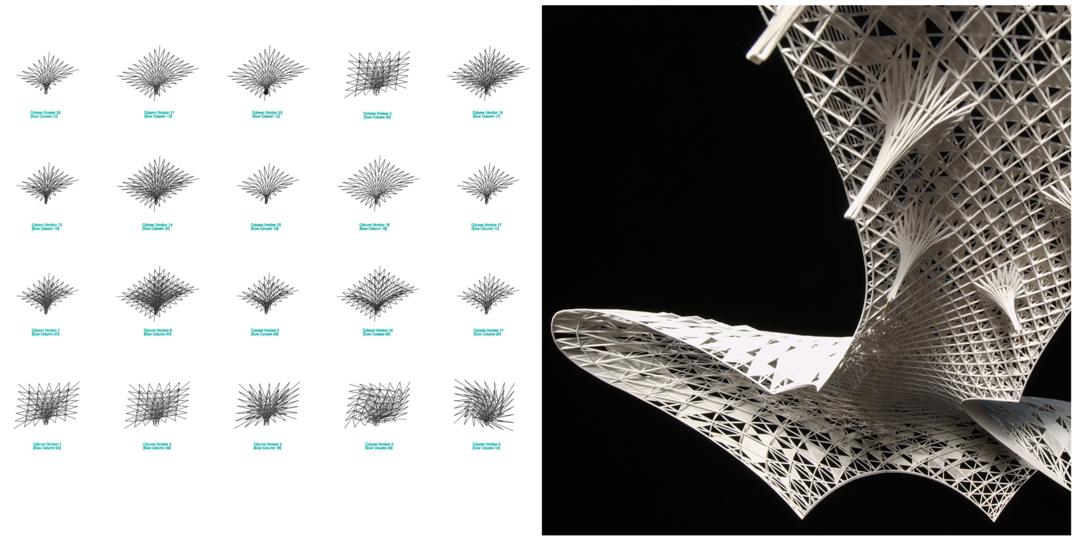
Image Source: Brady Peters / Foster + Partners
There were many different options for the spaceframe structure that were studied. The final version was an orthogonal top grid connected to a diagonal bottom grid. The computer program could generate all different options with centrelines for structural analysis. The column structures were one of the most challenging structures to design on the roof. The structural logic of the column continued the spaceframe logic of the roof itself. They were designed to look as though the roof structure was growing down to the ground. The column positions were very limited and were constantly changing due to the design of the architectural program underneath. The columns had to carry huge load – the wind uplift due to typhoons was apparently four times the dead weight of the roof itself. One of the most exciting aspects of this project was the learning of computer programming as a design tool. In this project, this then allowed the design of large fields of architectural components, the visual outcome which could not have been predicted beforehand.